Basic Structure of the Systems & Measurement Examples(3/4)
Four articles explain the understanding of birefringence and the measurement principles and features of our equipment.
Basic Structure
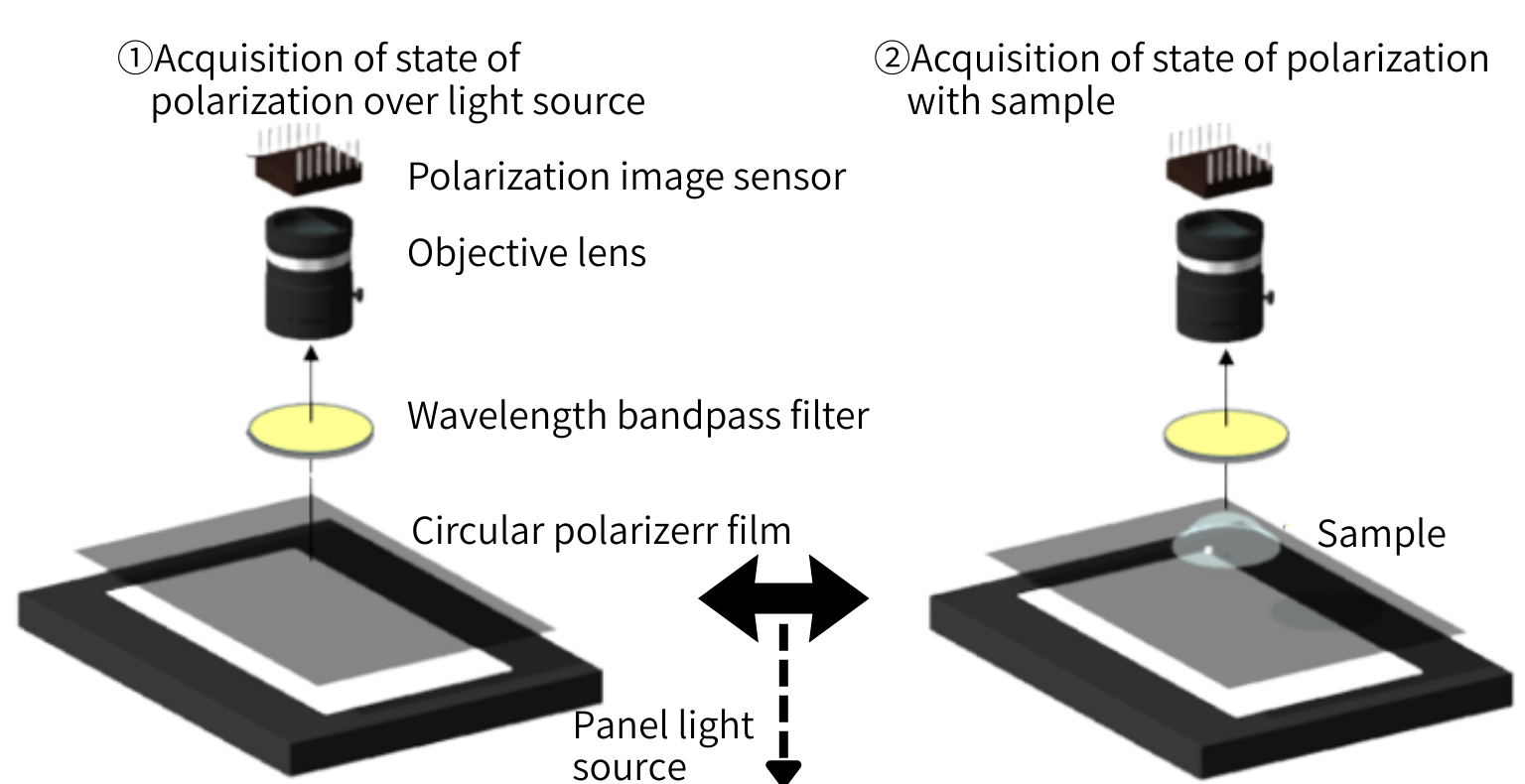
③Birefringence (phase shift & axis orientation) at each point by comparison of the states of polarization
Why using circular polarizer film:
If we used a linear polarizer, the regions of the sample having the same axis orientation as the film would not be correctly evaluated (no sensitivity).
Circular polarizer film allows to obtain the same sensitivity to birefringence independently from axis orientation.
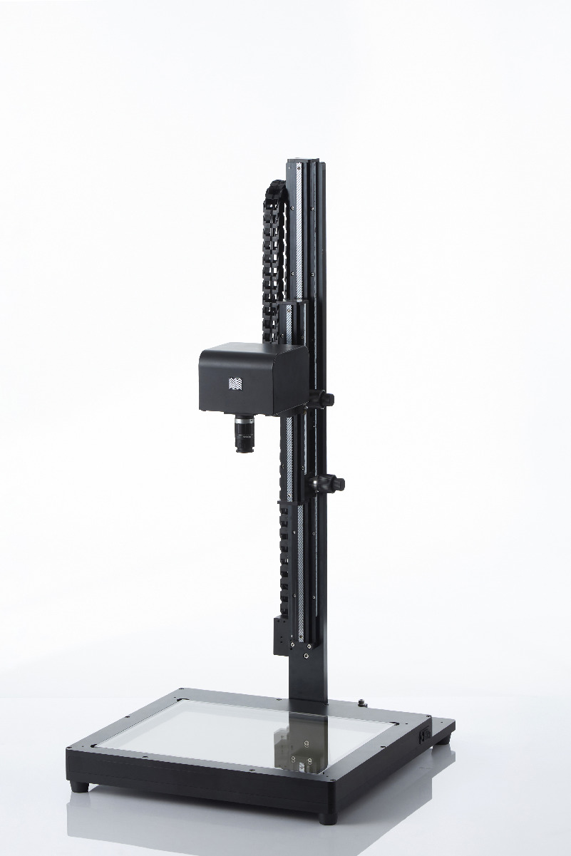
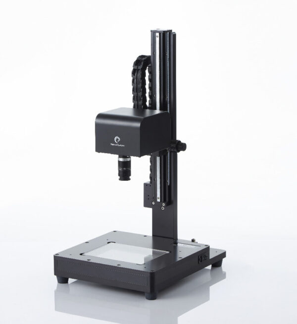
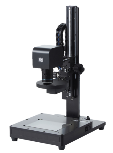
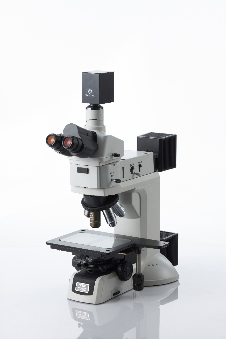
Actual system picture
PA System : Measurement Example (1)

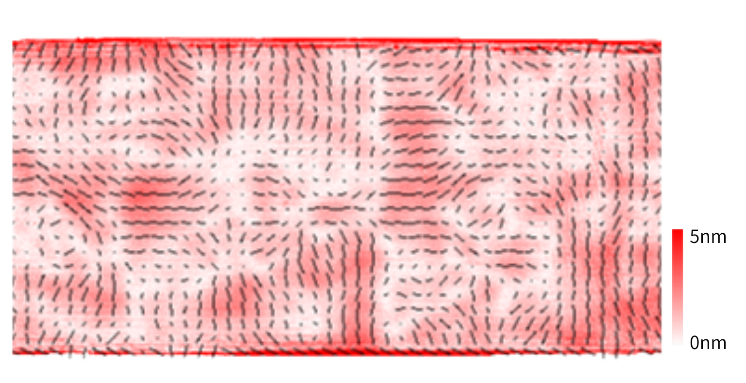
Plastic Molded Lens:
Distribution of Axis Orientation
Optical quality glass : phase shift distribution
PA System : Measurement Example (2)
PA Series include a model for microscopic applications, enabling evaluation of very small samples.
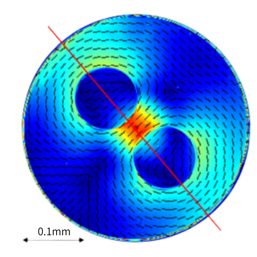
Measurement of birefringence distribution in an optical fiber cross-section
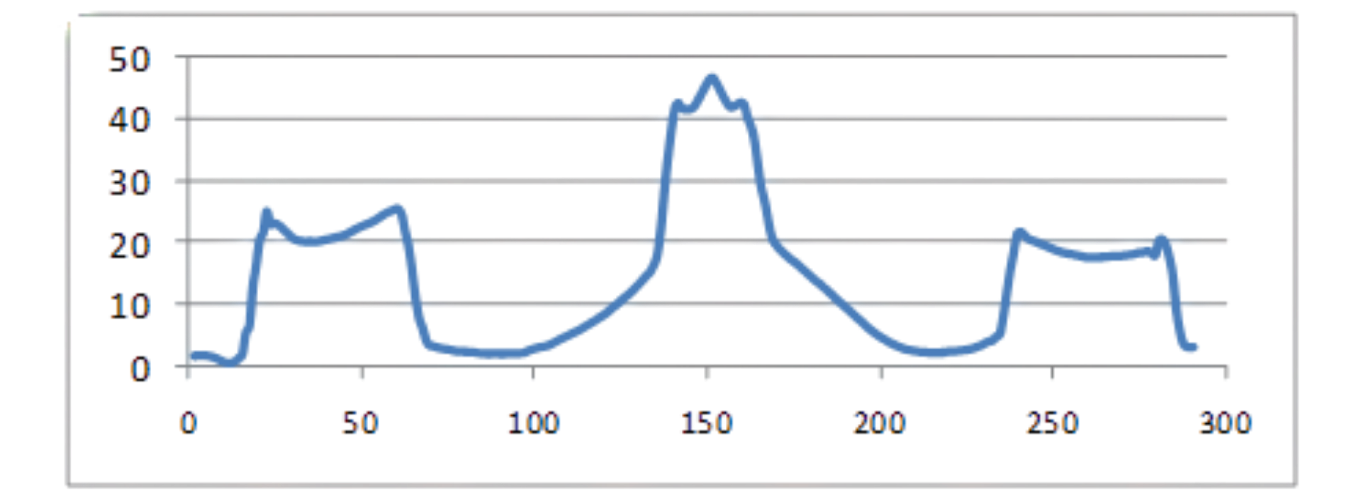
Graph along straight line
PA System : Measurement Example (3)
Plastic molded part (test piece) : evaluation of the differences between materials
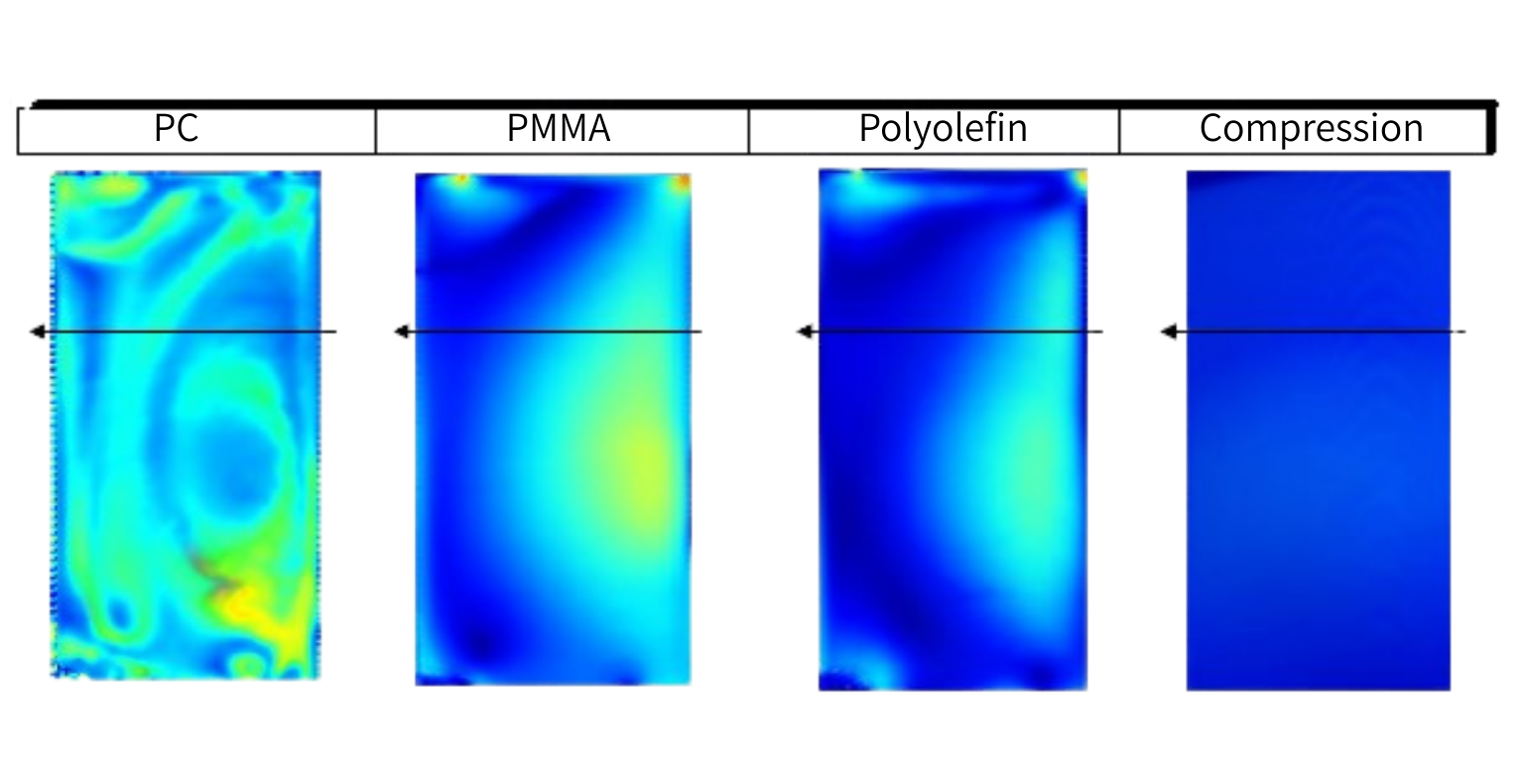
Differences of material & molding parameters appear clearly as differences in the birefringence profile.
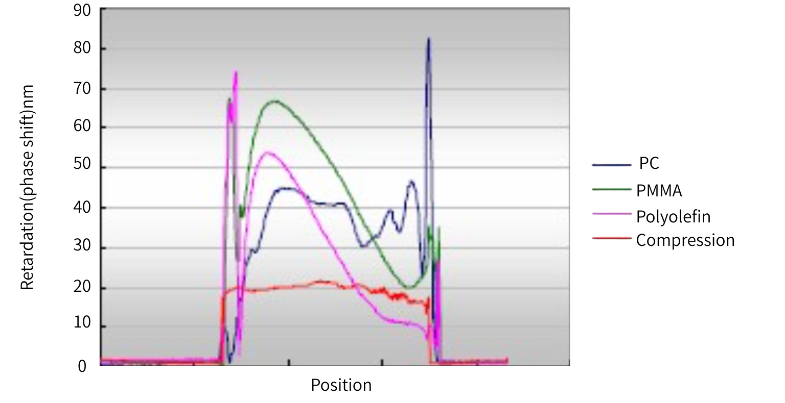
Phase shift along transversal line
※PC actually has the highest distortion. However, the phase difference is too large for the PA series to be measured correctly.
Range limitations of PA Series systems
The maximum birefringence that can be measured by PA system is λ/4.
Samples exhibiting greater retardation will be displayed with wrapped around values.
Evolution of recorded retardation for growing applied force on test piece (photo-elastic)
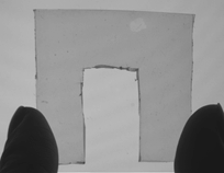
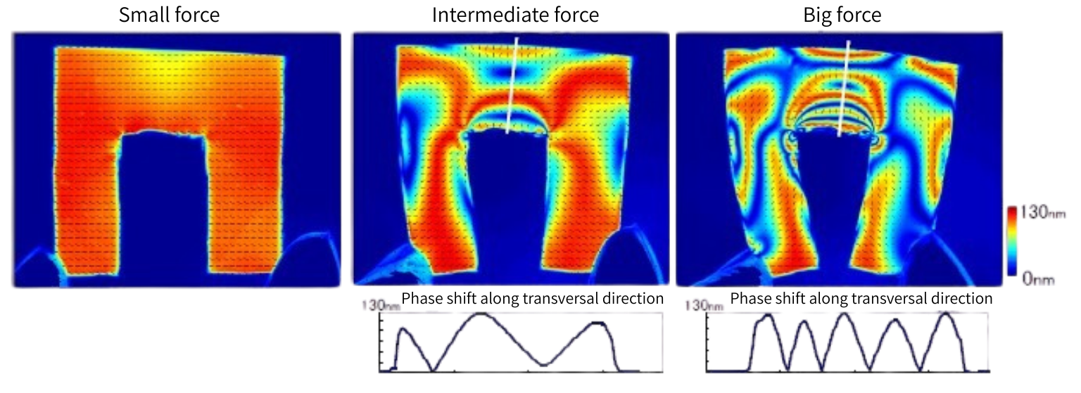
Values over ¼ of operating wavelength (520nm) are wrapped around.
It can result in ripples that do not exist in reality.
PA Series is limited to the evaluation of samples of less than 100nm of birefringence.
Continue to the next page