Basic principles of polarization ~Unveiling the enigmatic realm of glass/resin materials measurements~
About the Characteristics of Light
Light is composed of three elements: brightness, color, and polarization. Light is treated as a wave, and brightness can be thought of as the amplitude of the wave, color as wavelength of the wave, and polarization as the direction of oscillation of the wave.
Typically, we can see brightness and color with our eyes, but polarization is not discernible to the naked eye. This is the reason why it is difficult to intuitively understand. The human eye contains nerve cells called photoreceptors, but they do not have the ability to perceive polarization. This is because photoreceptors consist only of cone cells, which recognize color and shape, and rod cells, which detect brightness.
Types of Polarization
Polarization refers to light vibrating or oscillating in a specific direction.
There are several types of polarization.
- Linear Polarization(LP): Light in which vibrations occur in a straight line.
- Circular Polarization(CP): Light vibrating while tracing a circular path.
- Elliptical Polarization(EP): Light vibrating while tracing an elliptical path.
- Random Polarization(RP): Light without a specific direction of vibration.
For example, sunlight and fluorescent light exhibit random polarization.
Figure 1 shows the trajectory of polarization observed in a flat plane.
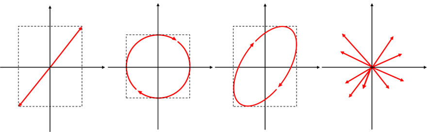
Figure 1: Types of Polarization (Linear Polarization, Circular Polarization, Elliptical Polarization, Random Polarization)
Also, the following image shows the vibration of light in a moving image.

.gif)
A polarizing Element
A polarizing element is used to generate polarized light, also called a polarizer. Polarizers have a transmission axis with a fixed direction, and only linearly polarized light that oscillates in the same direction as the transmission axis is allowed to pass through.
With a single polarizing element, the polarization of light that passes through is determined by the orientation of its transmission axis. For example, when two polarizing elements with the same orientation are stacked, light can pass through (Figure2: Left). When the orientations of the transmission axes differ, light transmission becomes less effective, and when the axes are orthogonal, light does not pass through (Figure2: Right). Figure 3 illustrates an example of two polarizing elements with transmission axes at different angles.
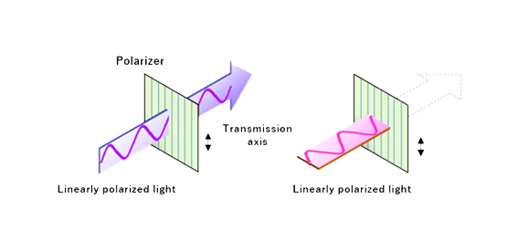
Figure 2: LP with transmission axis in the same direction (Left) LP with transmission axis perpendicular (Right)
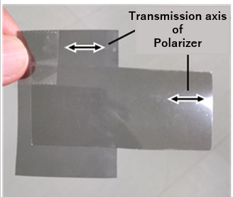
Figure 3: Transmission axes are Parallel
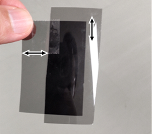
Figure 3: Transmission axes are perpendicular
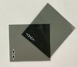
Figure 3: Transmission axes are at 45°
As mentioned earlier, light passing through a polarizing element can create LP.
Polarization states include LP, CP, and EP. Most light passing through familiar materials such as cellophane tape is elliptically polarized, but special elements such as polarizing plates are needed to create LP or CP.
Figure 4 shows the polarization state: the red line represents LP, the center represents CP, and the interior of the red circle represents EP. For example, consider the image of throwing a dart, the light passing through the cellophane tape is similar to how a dart pierces the target. If the dart strikes in the center, the light is circularly polarized; if it strikes on the red line, the light is linearly polarized; and if it strikes anywhere else, the light is elliptically polarized.
This illustrates that obtaining LP or CP requires precise manipulation of light in specific directions or methods.
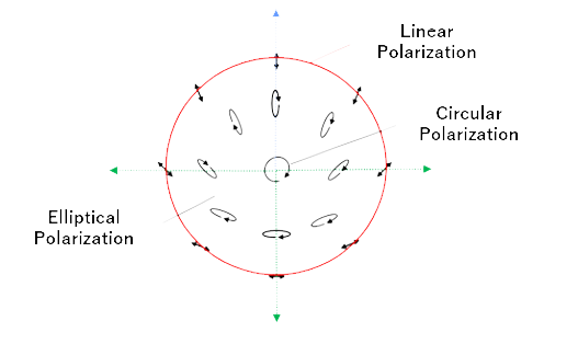
Figure 4: Partial representation of Polarization States
Superposition of horizontal and vertical waves
Various polarization states shown in Figure 1 can be represented by combining LPs in the vertical and horizontal directions. Specifically, combinations of vertical and horizontal LPs produce polarization states such as CP and EP. Movies 2 and 3 below demonstrate this process.
To create these different polarization states, the amplitude and phase difference of the two LPs are varied. Amplitude represents the magnitude of the wave, and phase difference represents the misalignment of the peaks and troughs of the two waves. By changing the combination of amplitude and phase difference, various polarization states can be obtained, ranging from LP to CP.
Materials such as polarizers and cellophane tape serve to control the amplitude and phase difference of LPs in the vertical and horizontal directions. This ability allows them to generate specific polarization states.
Movie 2 shows LP (Green: composite wave, Blue: wave oscillating in the vertical direction, Red: wave oscillating in the horizontal direction)
Movie 3 shows LP (Green: composite wave, Blue: wave oscillating in the vertical direction, Red: wave oscillating in the horizontal direction)
Birefringent Materials
Many plastic materials exhibit birefringence. This is a phenomenon in which the refractive index differs depending on the direction of light oscillation(polarization), or includes the refractive index differing depending on the direction of light incidence. Materials with higher refractive indices take longer for light to pass through.
The phase difference δ characterizing the polarization state is expressed by taking into account the effects of birefringence with the following equation:
δ=Birefringence Δn × Thickness of the material d
Here, Δn represents the refractive index due to birefringence, and d is the thickness of the material.
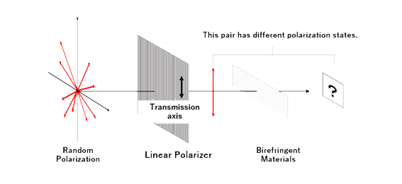
Figure 5: Randomly polarized light passed through a linear polarizer and birefringent material
Figure 5 shows what occurs, when random polarized light is passed through a polarizer (linear polarizer), the polarization state of the light is converted to LP. Then, when this linearly polarized light is passed through a material with birefringence, such as cellophane tape, a new polarization state is generated.
In birefringent materials, the refractive index varies depending on the polarization direction (polarization) of light, which affects the polarization state of the light that passes through the material. Therefore, when linearly polarized light passes through cellophane tape, the light may be converted to a new polarization state (such as elliptical polarization) due to the birefringence of the cellophane tape.
Thus, by combining polarizers and birefringent materials, the polarization state of light can be controlled to address various applications.

Movie 4: Linearly polarized light in birefringent materials such as cellophane tape
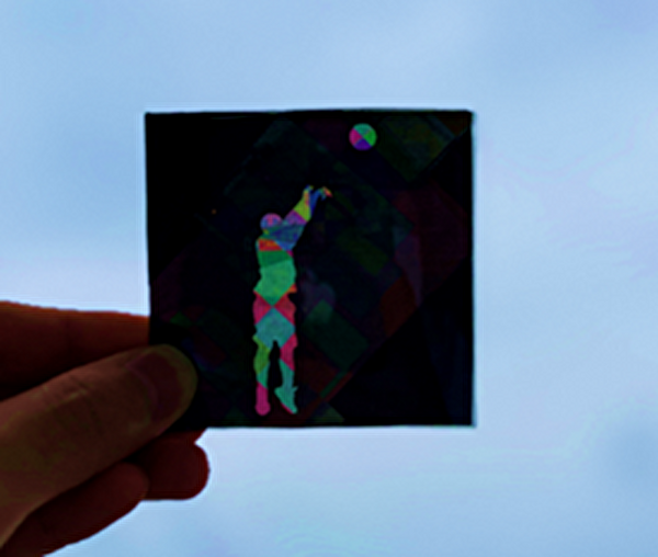
As a concrete example for better understanding, consider why cellophane tape looks colorful. As an example, we will use two wavelengths of light: red (600 nm) and blue (300 nm). Each of these wavelengths can be broken down into vertical waves, which oscillate vertically, and horizontal waves, which oscillate horizontally (see the superposition of horizontal and vertical waves).
Assume that the refractive index differs regardless of color (wavelength) as it passes through a birefringent material. For example, in a material through which red and blue light pass, the refractive index of the vertical wave is 1 and that of the horizontal wave is 2.
As mentioned above, vertical and horizontal waves have different speeds, so even if they travel the same distance, there will be a time discrepancy (because the vertical wave travels faster). This causes a phase difference between the peaks of the vertical wave and the horizontal wave. The phase difference is represented by the progress of the bars in Figure 6 below.
For example, let’s consider a phase difference of 300nm after passing through a birefringent material. If red and blue light pass through the same 300nm, it means that the vertically polarized wave is delayed by half a wavelength compared to the horizontally polarized wave, whereas for blue light, it is delayed by a full wavelength.
Therefore, the polarization state of light after passing through a birefringent material varies with wavelength (color). Remember that the polarization state is expressed in terms of phase difference and amplitude. Although the human eye cannot directly perceive the polarization state, the brightness (intensity) of light after passing through a polarizer (linear polarizer) differs depending on the color, making the superposition of the three primary colors appear visually colorful.
The greater the number of layers of cellophane tape, the greater the phase difference. As a result, the polarization state of light differs greatly depending on the wavelength (color), and the brightness of light after passing through the polarizing plate changes markedly depending on the color.
Look at Movie 5 to observe how vertical and horizontal waves shift when passing through a birefringent material. The movie shows conditions where the longitudinal refractive index is the same as air and the transverse refractive index is very high.
It can be understood that the difference in the refractive index between the longitudinal and transverse directions causes a difference in the speed of the wave, which in turn causes a phase difference and changes the polarization state of the light.
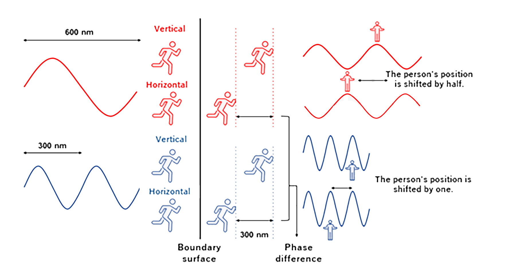
Figure 6: Illustration depicting phase difference using a stick figure.
Movie 5: Phase difference generated by transmission through birefringent material (material with different refractive indices vertically and horizontally)
Summary
Thank you for reading to the end, we understand this is a lot to take in.
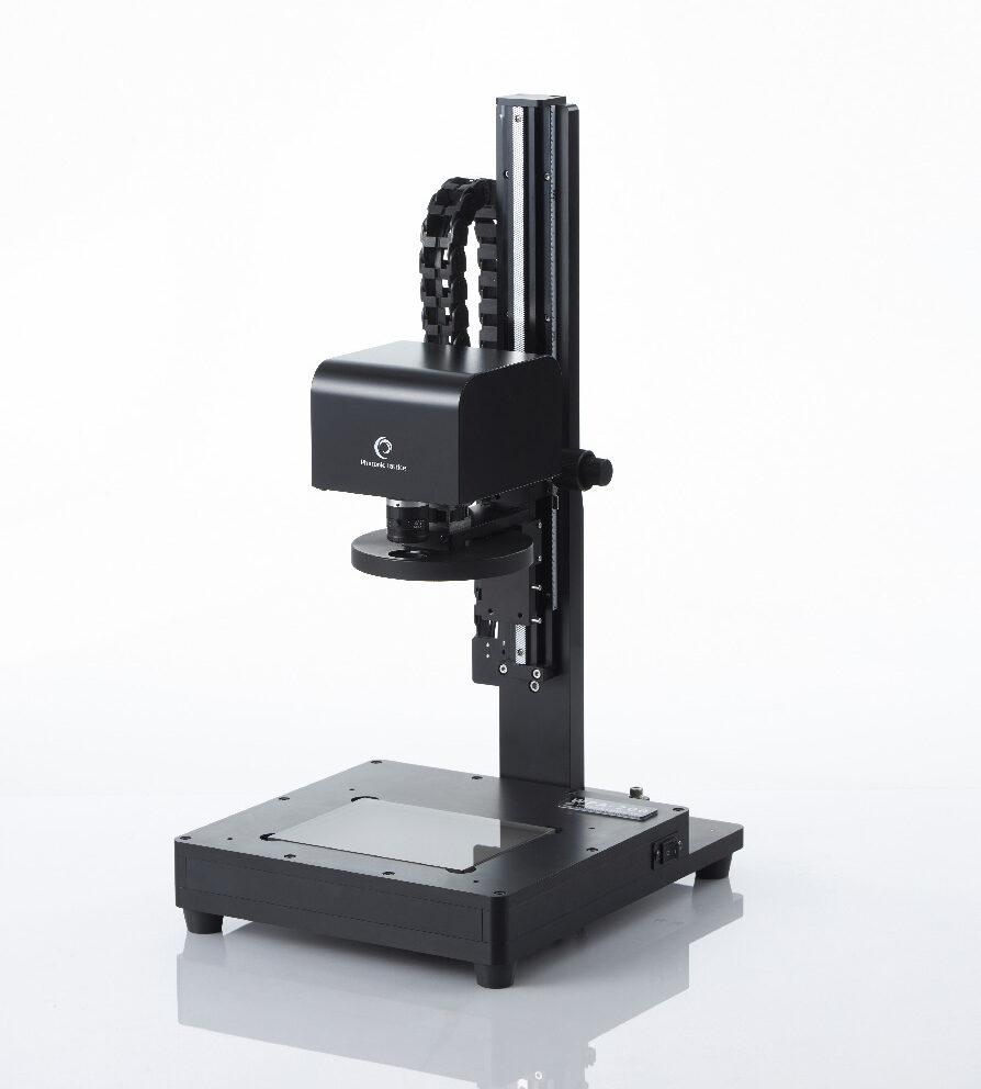
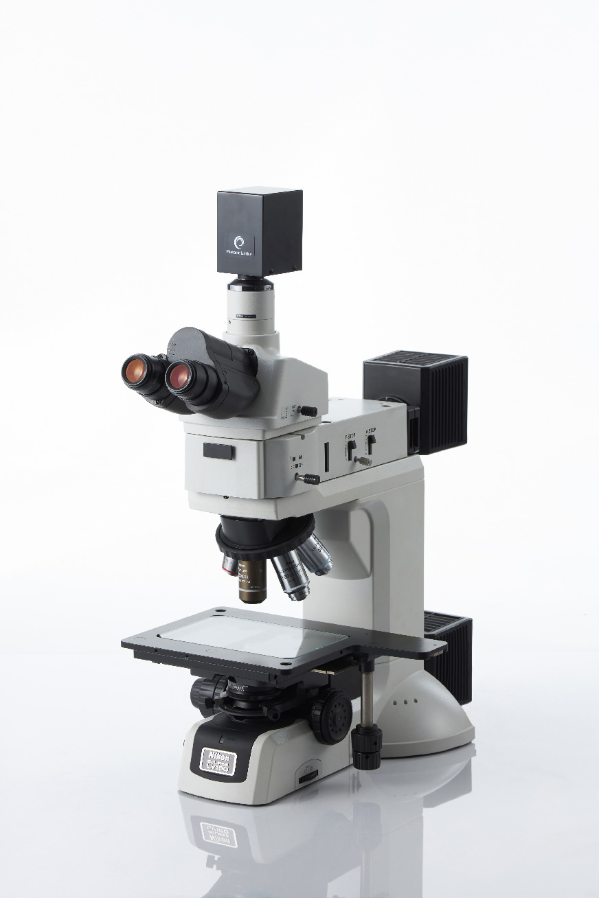
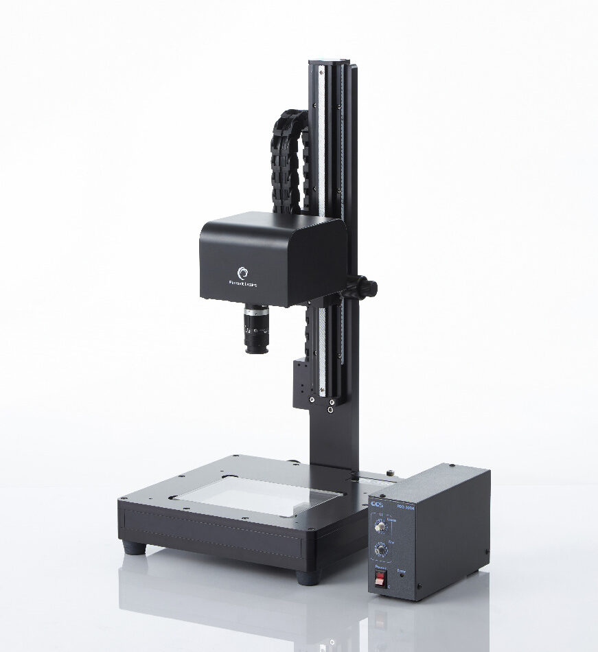
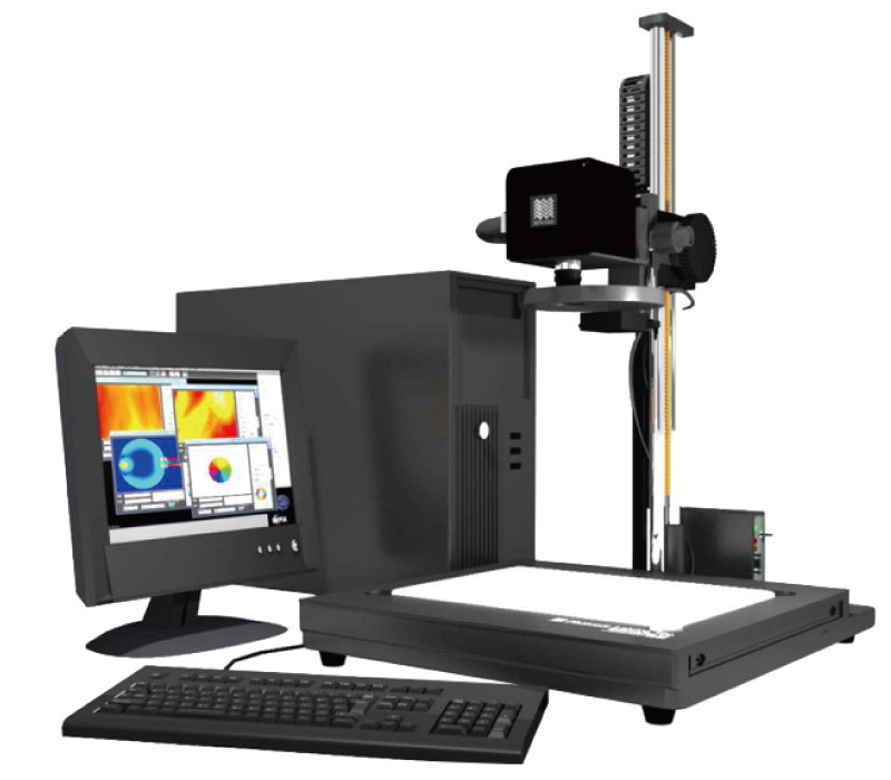
We manufacture and sell devices that apply this property of light to evaluate birefringence.
If you’re interested in more detailed articles about this technology, please look here.
This is a total of four articles on birefringence.